

Abstract
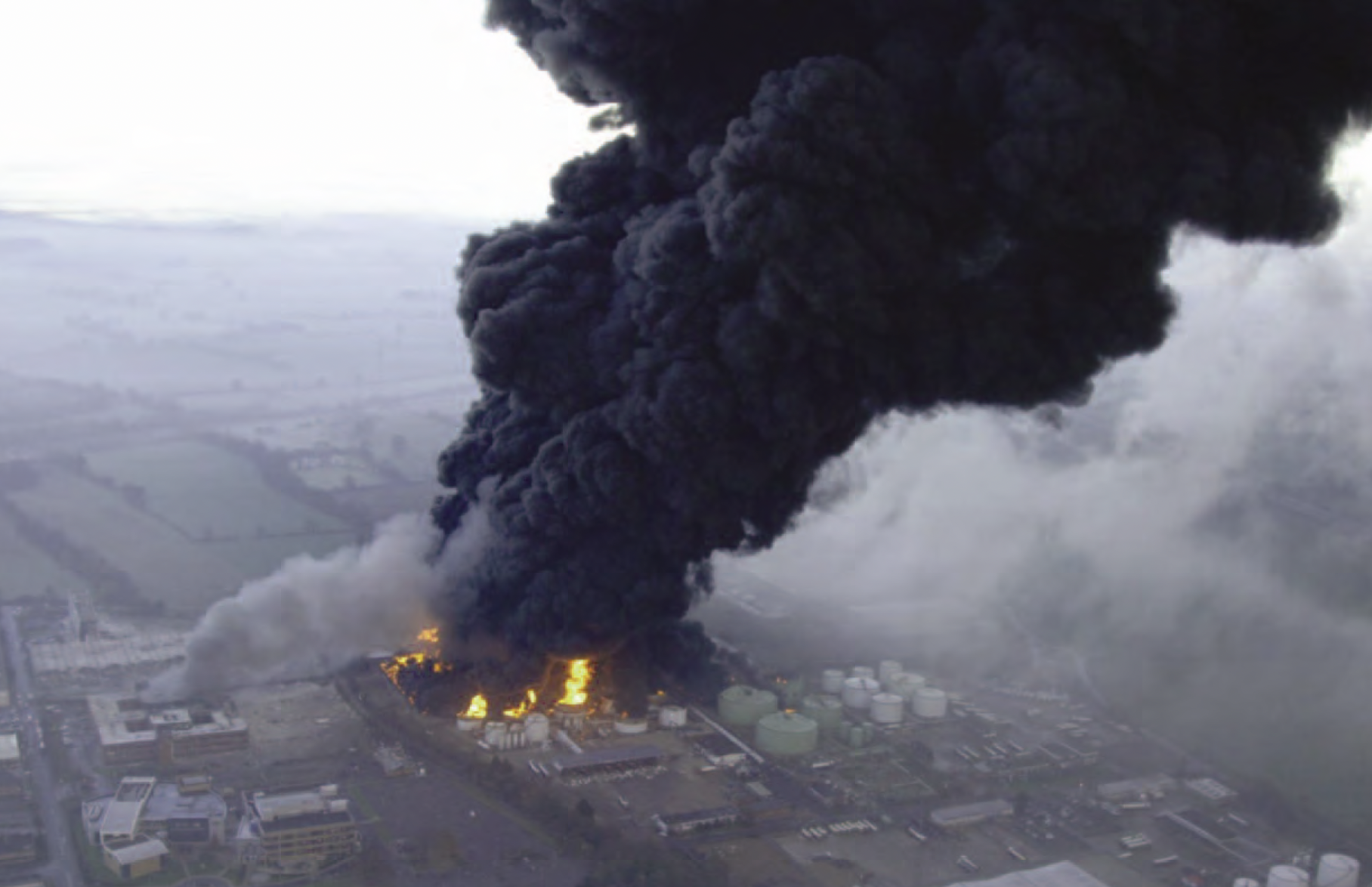
At 6:00 am on Sunday December 11, 2005 a large explosion occurred at the Buncefield Oil Storage Depot. The explosion destroyed a significant section of the depot and caused widespread damage to homes and businesses surrounding the site. Overfilling of one of the storage tanks caused a release of 300 tons of unleaded gasoline and created a very large vapor cloud (>120,000 m2). The ignition source of the cloud was likely an emergency pump house. The explosion resulted in very large overpressures (> 2bar), which caused significant damage to neighboring commercial and residential structures. Broken windows were observed up to 8 km (5 miles) from the site.
Due to the severity of the event, the Buncefield Major Incident Investigation Board (BMIIB) was formed in January 2006 to oversee the investigation. In order to achieve very large overpressures in unconfined vapor cloud explosions, a large number of obstacles are required to cause turbulence and flame acceleration, which further causes turbulence ahead of the flame front. While investigative groups have for a number of years been aware of the potential for flame acceleration and overpressure generation due to obstacles in gas clouds, the Buncefield depot was relatively uncongested and could not cause the observed overpressures. In fact in May 2006, the BMIIB concluded that, “The magnitude of the overpressures generated… is not consistent with current understanding of vapour cloud explosions. … The investigation has, so far, been unable to establish why the ignition of the vapour cloud and the explosion propagation… caused significant overpressures that produced the severe damage to property.” In addition, the blast damage indicators appeared to have contradicted the location of the ignition source, where objects were blown towards instead of away from the ignition source.
Gexcon was contacted by one of the facility owners to help in the investigation of this large explosion. Initial site inspections showed that alongside the roads surrounding the site (Buncefield Lane and Three Cherry Trees Lane), dense vegetation in the form of trees and bushes was present. Using the explosion simulator FLACS, the geometry of the Buncefield site was modeled including the dense vegetation. A large, shallow, heavier-than-air gas cloud was defined to cover part of the site and surroundings. Upon ignition a flame was established in the gas cloud. This flame accelerated through the trees along the surrounding roads, and resulted in high overpressures of several bar being generated by FLACS. In addition, FLACS simulations predicted strong convective flow towards the ignition source and reconciled the observed blast damage indicators. To our knowledge this is the first time the effect of trees on explosions has been demonstrated by 3D analyses. To further demonstrate the validity of these results, a set of experiments was performed to demonstrate that congestion caused by dense vegetation could cause the same flame accelerations. The main conclusions of the study are that trees can have an influence on flame acceleration in gas-air clouds, and that advanced models such as FLACS can be used to study such influence.
Introduction and background
At 6:00 am on Sunday December 11, 2005 a large explosion occurred at the Buncefield Oil Storage Depot (see Figure 1). The explosion destroyed a significant section of the depot and caused widespread damage to homes and businesses surrounding the site. Overfilling of one of the storage tanks caused a release of 300 tons of unleaded gasoline and created a very large vapor cloud (>120,000 m2). The ignition source of the cloud was likely an emergency pump house. The explosion resulted in very large overpressures (> 2bar), which caused significant damage to neighboring commercial and residential structures.
The Buncefield Major Incident Investigation Board (BMIIB) was formed in January 2006 to oversee the investigation. While investigative groups have for a number of years been aware of the potential for flame acceleration and overpressure generation due to obstacles in gas clouds, the Buncefield depot was relatively uncongested and could not cause the observed overpressures. In fact in May 2006, the BMIIB concluded that, “The magnitude of the overpressures generated… is not consistent with current understanding of vapour cloud explosions. … The investigation has, so far, been unable to establish why the ignition of the vapour cloud and the explosion propagation… caused significant overpressures that produced the severe damage to property.” In addition, the blast damage indicators appeared to have contradicted the location of the ignition source, where objects were blown towards instead of away from the ignition source.
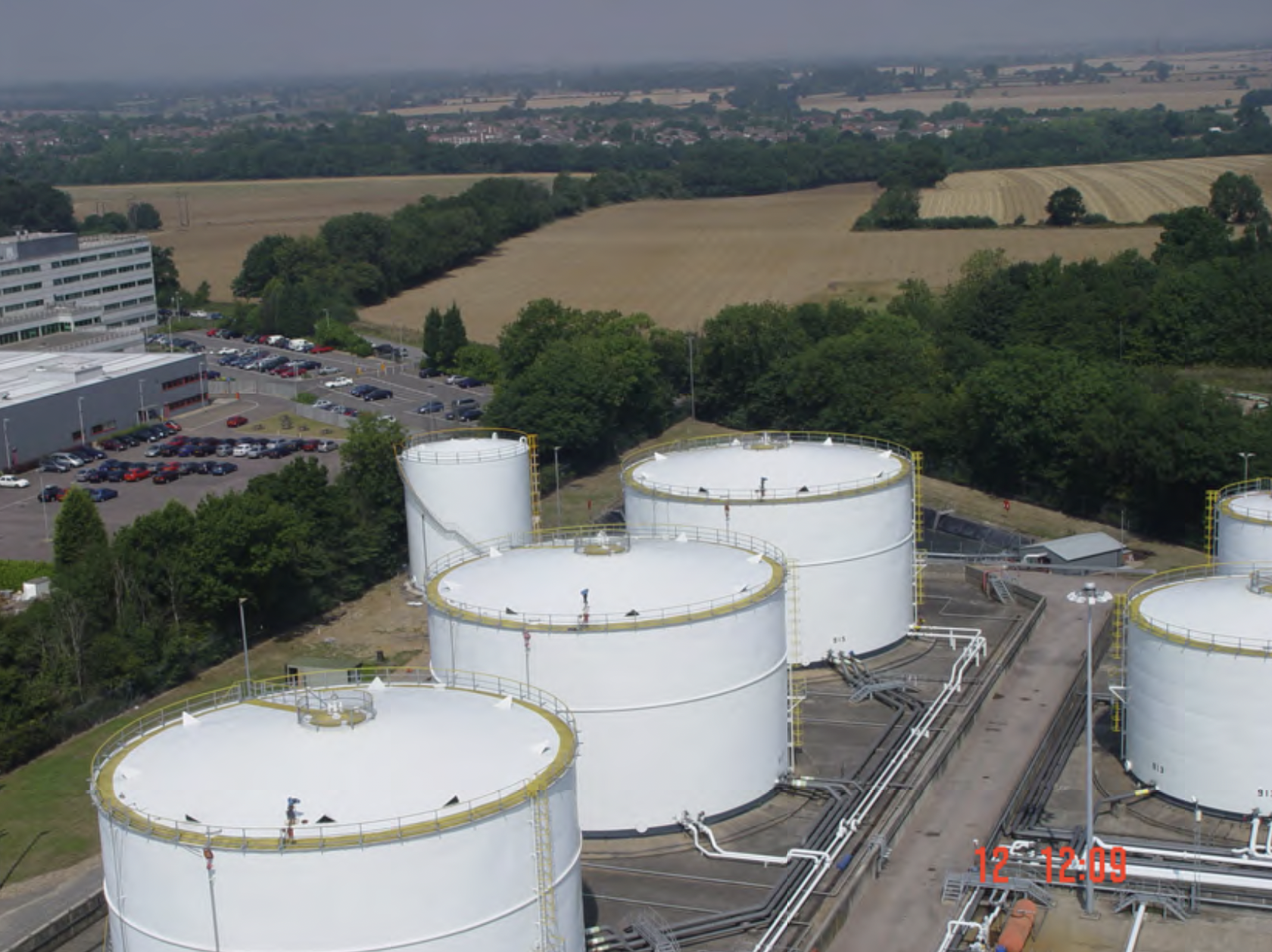
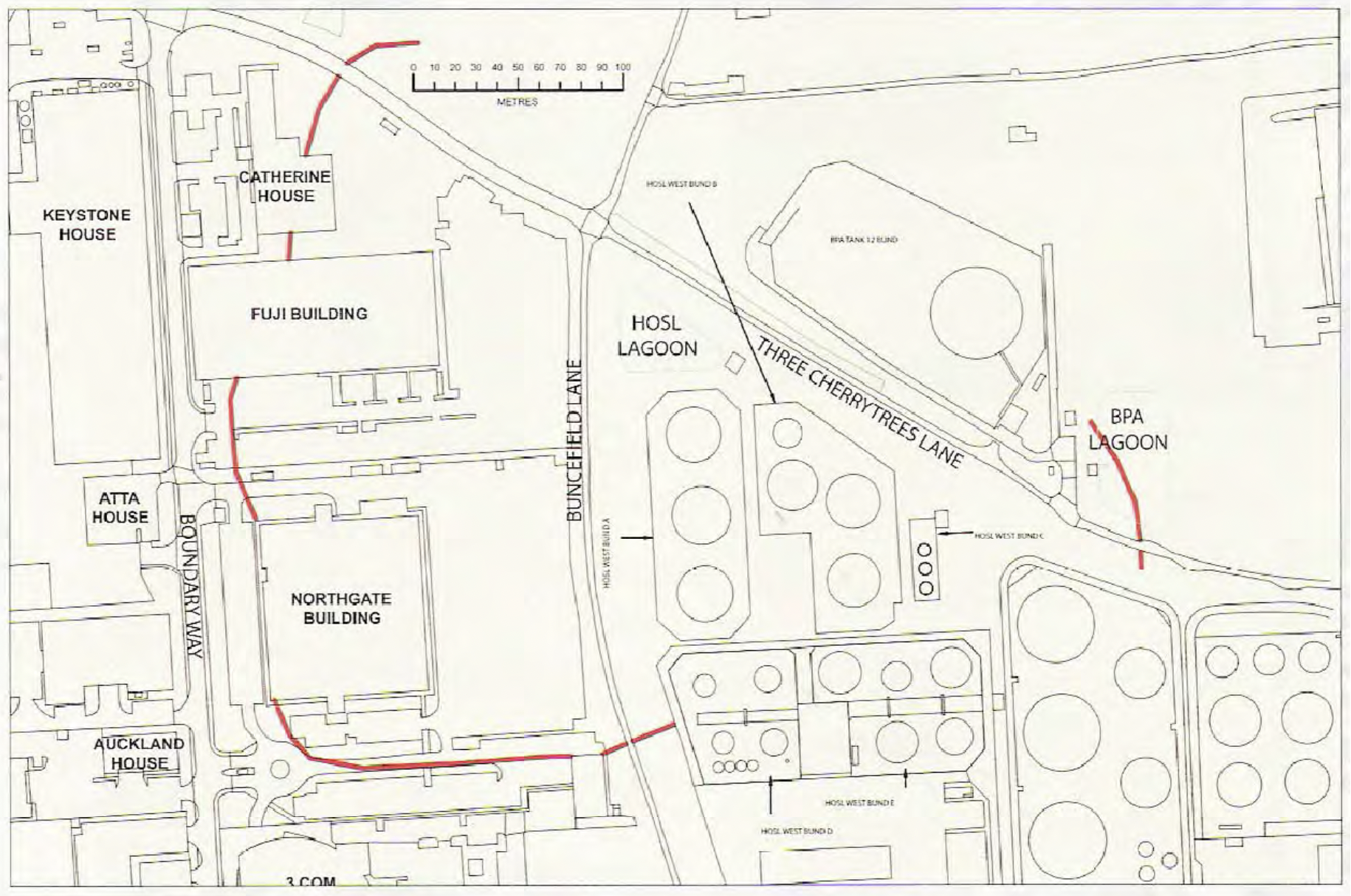
Gexcon was contacted by one of the facility owners to help in the investigation of this large explosion (1). Figure 2 shows the northern part of the site before the accident. The present study was performed to simulate probable explosion scenarios and to attempt to reconcile the damage evidence with the explosion simulations.
The two main goals of the present study were to:
- provide a foundation for establishing the probable cause of the incident, and
- understand the governing physics and mechanisms that participated in the explosion
The computational fluid dynamics (CFD) explosion program FLACS, which has been validated against hundreds of explosion experiments, was used in the study. FLACS simulates the three-dimensional development of explosions through clouds of vapor mixtures in complex geometries. It produces a time history of effects such as flame progression through the vapor, explosion pressure development, blast wave propagation, and transient blast wind at all locations covered by the geometry model.
Analysis
Geometry model of Buncefield
A major physical survey of the site was undertaken on June 27, 2006, resulting in extensive photos, video survey and some actual measurements. It was particularly noted that the congestion levels of equipment, tertiary structures, pipes and electrical items on the Buncefield site was assessed to be very low (i.e., below the threshold for causing significant explosion pressures).
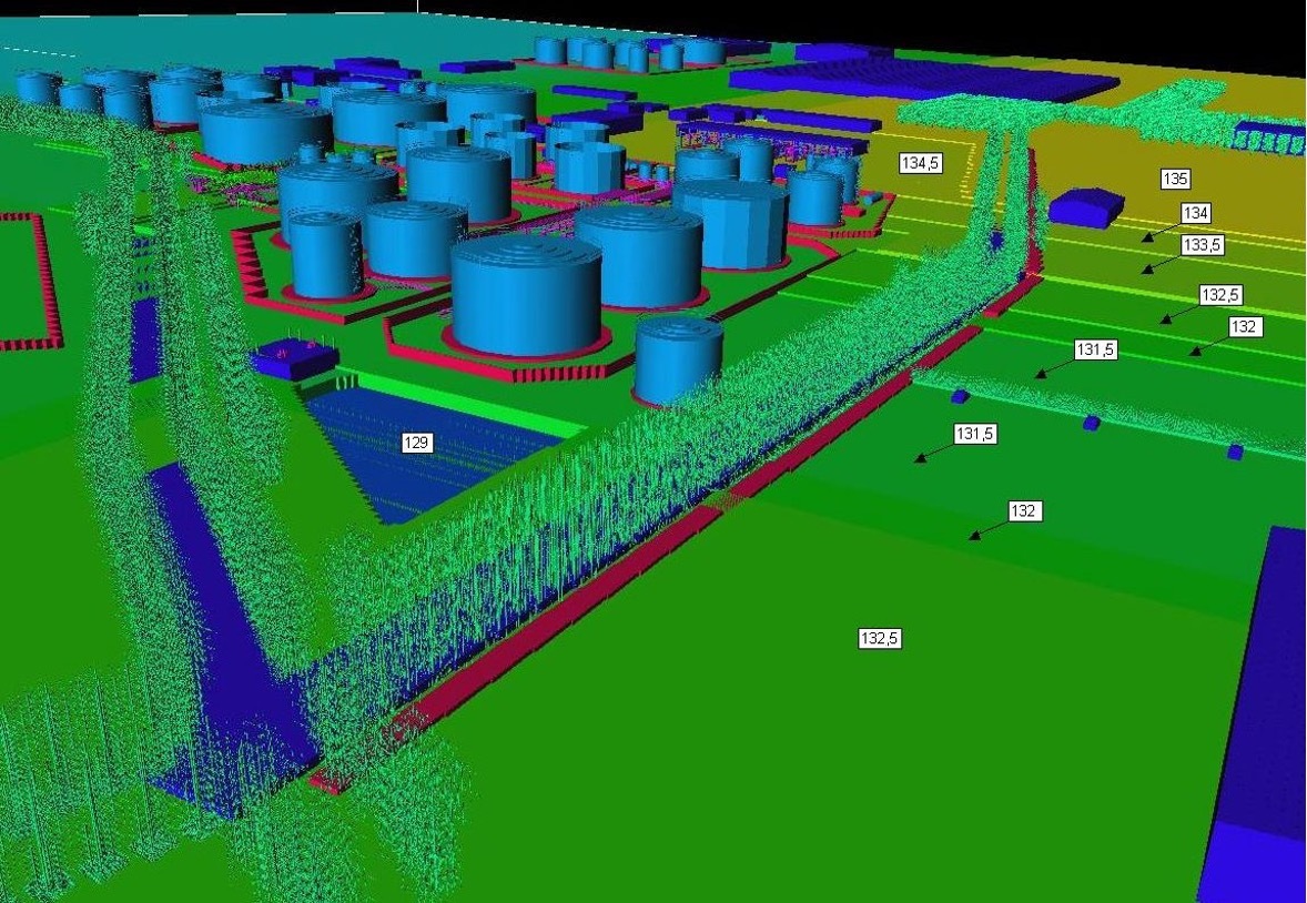
The observed off-site damage, with notable severity in the areas of the Fuji / Northgate car parks and to the trees in parts of Buncefield Lane and Three Cherry Trees Lane, brought attention to the potential congestion in that area (i.e., namely the trees themselves). What was unusual was that the avenues of trees that bordered these lanes were heavily coppiced instead of having a trunk and spreading crown at some distance above the ground. In addition, the dense bramble undergrowth along Buncefield Lane was also considered to be a potential source of congestion. When evaluating the level of “congestion” (meters of branches per cubic meter of volume) it was found that it was at least as high as that of pipework in densely congested process areas. Hence a very detailed FLACS model was constructed, with particular emphasis on the congestion formed by trees along Three Cherry Trees and Buncefield Lanes (see Figure 3).
Simulation scenarios
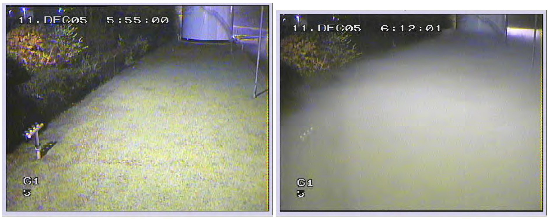
Based on CCTV footage, estimates were made of cloud depth (vertical extent) to use in the FLACS simulations. It was assumed that the visible part of the cloud is a lower limit to cloud depth. Since there is no known correlation between cloud concentration and cloud visibility, it was taken to be reasonable that the height of flammable gas was perhaps slightly higher than the visible cloud. The most realistic cloud depth was then taken to be of the order of 5 m based on a reference point in the images. Cloud depth will vary since in the simulations the top is kept at fixed height but the ground is not at the same elevation everywhere.
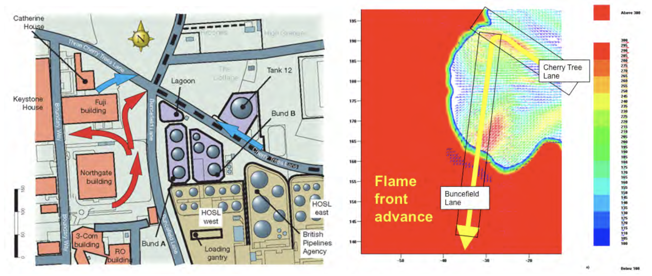
Figure 4 shows the cloud spread over a 17 minute period in the area just to the west of T912 and the visible part has increased to 4.5 to 5m above the tank base in this time. It is not clear how much the cloud increased in thickness subsequently or to what extent the vapor cloud extends above the visible mist. The visible mist was likely a condensed water mist or it could have been an aerosol of fuel droplets, or a combination of both. Based on the final report of the BMIIB (volume 2), the horizontal cloud extent was approximated to be from between the Northgate and Fuji buildings in the west and to the BPA lagoon in the east (see Figure 5) and from south of Northgate building to north of Catherine house in the north-south direction.
For the purpose of the simulations the cloud is assumed to consist of a homogeneous mixture of butane and air at stoichiometric concentration. This is likely to be a simplification of the actual cloud composition; however, if the cloud were to consist of a combination of gas-air at lean concentration and with droplets making up the remaining fuel in the air, the stoichiometric assumption may very well be a reasonable one. Experiments (2) show that for fuel blends (e.g., crude oil) of most clouds containing components of both high and low volatility; overpressures do not decrease with increasing fuel concentration.
Ignition was assumed to take place in the pump house close to Three Cherry Trees Lane and the HOSL lagoon. The time of ignition coincided within a few seconds with starting the fire pumps. The pump house walls and roof were taken to rupture at relatively low overpressure (0.1 barg for the north wall, 0.15 barg for other walls and roof). This would lead to a high-speed, turbulent, sizable flame jetting out to atmosphere and particularly into the tree growth along Three Cherry Trees Lane.
Explosion simulation results
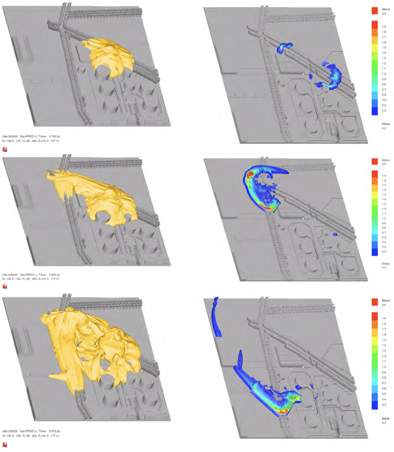
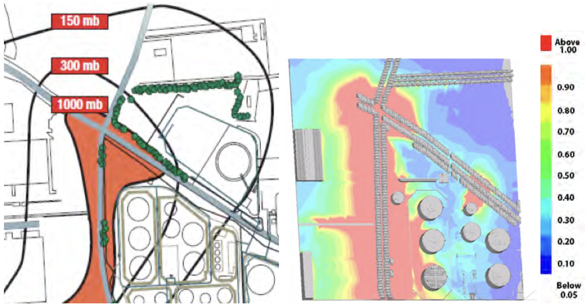
Figure 6 shows both the flame development results (left) and overpressures (right) for an explosion in a 5m tall cloud. For this case, the pressures are shown between 0.2 and 2 barg, with zones of higher pressure all being in red. In fact, overpressures reached as high as 10 barg for this simulation of an explosion in a 5m cloud. Figure 7 shows that the simulated explosion overpressures agreed very well in both magnitude and location with the estimated overpressures provided in the final report of the BMIIB final report (volume 2). Notable examples include how closely the simulated 300 mbar overpressure in the vicinity of Fuji building agreed with the 300 mbar isobar estimate from blast damage.
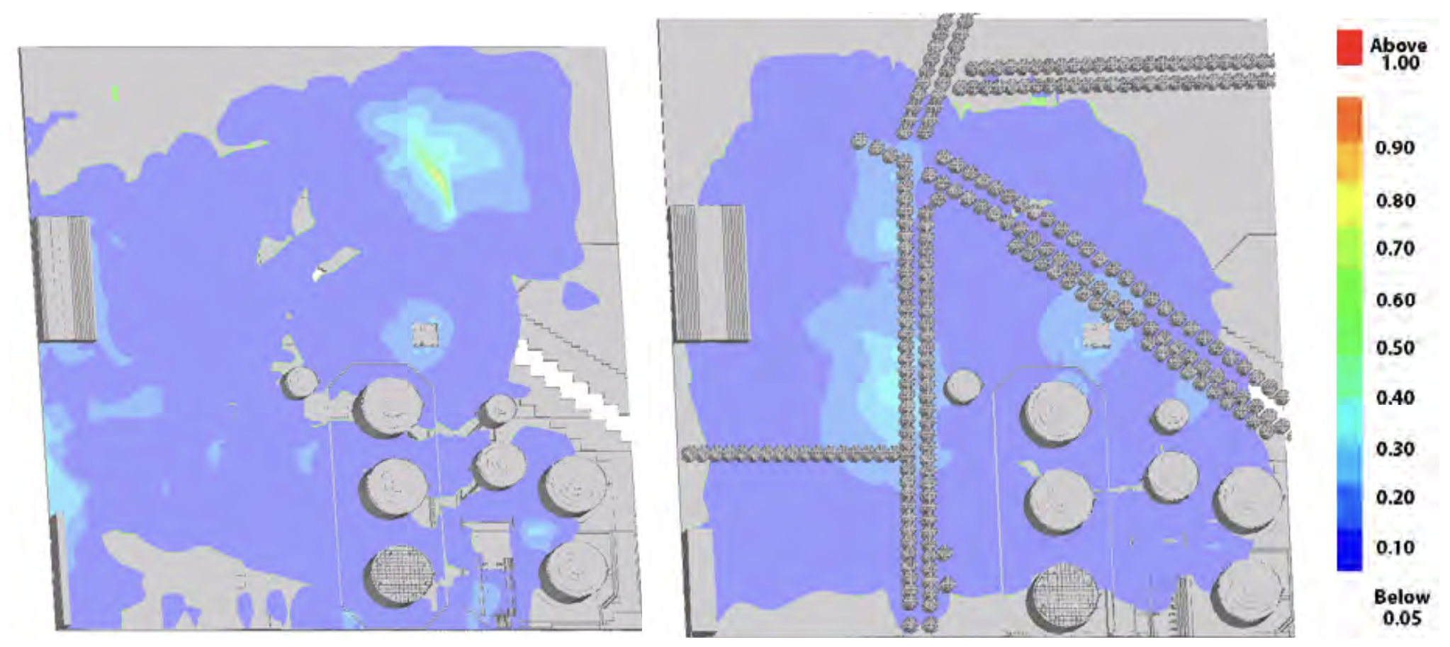
Of note is that simulations performed with the same massive flammable gas cloud (5m high cloud), but with no trees or more traditional trees with large trunks (Figure 8), give very low overpressures and relatively slow flame development, as would be expected for the uncongested tank farm. Except at the pump house where ignition takes place, localized maximum overpressures do not typically exceed 200-300 mbarg and are typically 100 mbarg for most of the involved region. Trees and undergrowth have not hitherto been modeled in FLACS analyses. The reason why they were in this study is that they constituted the only congestion in the area near where damage was observed, and hence where explosion overpressures were probably highest. Also the density of the coppiced trees and undergrowth was exceptionally high, as was found in the survey in June 2006.
The explosion simulations using actual extremely dense vegetation show that the very long run-up distances in the highly congested regions caused significant flame accelerations that quite possibly transitioned to detonations. While FLACS does not model detonations, the blast overpressures and propagation, as determined from the movement of objects, can equally be described by fast deflagration or non-detonation conditions. Figure 9 shows that FLACS simulations predicted a very strong convective flow towards the ignition source (opposite of flame propagation) and agree very well with the observed blast damage indicators cited in the BMIIB final report (volume 2).
A response simulation of small branches was performed to test whether small branches and undergrowth would simply be bowled along in the accelerating flow that precedes the violent combustion at the flame front of the explosion, rather than act as a generator of turbulence. It turned out that once the flame acceleration process was established, the acceleration is so sharp that the small branches contribute to congestion more or less like a matrix of rigidly fixed small pipes of the same size and geometrical make-up.
FLACS explosion simulation of the Buncefield depot
Experimental work
As described above the strength of the Buncefield explosion could be attributed to a positive feedback mechanism between combustion generated turbulence at trees surrounding the depot and the combustion itself. Although the interaction of combustion generated flow and the subsequent turbulence generation in congested industrial areas and its influence on the combustion is a well-documented phenomenon both experimentally and theoretically (3), (4), (5), (6), (7), (8), (9), the influence of vegetation on the course of flame propagation in clouds encompassing vegetation has however never been addressed experimentally.
While experimental studies have not been conducted, the influence of vegetation may have played an important role in certain explosion accidents. The most paramount example is the Ufa-accident of 1989 (in the Ural Mountains in Russia), which happened in a valley in a dense forest area after a pipeline rupture involving LPG. The ignition occurred when two passenger trains travelling in opposite directions entered the cloud (10). The explosion killed 575 people and wounded 623.
Below the results of a preliminary experimental program aiming at determining whether vegetation can affect flame propagation contributing to blast generated by vapor cloud explosions are presented (11).
Experimental results
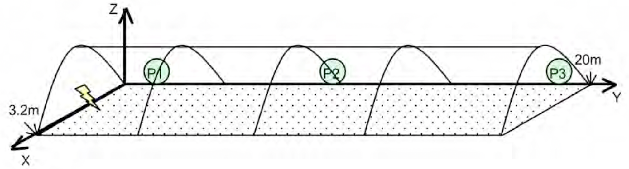
The test volume retaining the gas cloud, shown in Figure 10 consisted of a plastic-covered tunnel that was 20 m long with a semi-circular cross-section 3.2 m in diameter. The total volume of the tent was approximately 80.4 m3. The plastic tent released at very low overpressures as to minimally affect the explosion. A gas recirculation system was used to prepare gas mixtures inside of propane in air (4.0-4.2 % vol). A high voltage, long duration, oscillating electric spark was used to ignite the propane-air mixtures (see Figure 10). Explosion pressures along the center at 1m, 10.5m and 19.7m from ignition source and flame speeds (using high-speed video) were the main parameters measured.
A total of 5 tests were performed. Test 1 was intended to be a reference test for subsequent tests and was performed without primary obstructions. Tests 2 and 3 were performed with one and two rows of small bushes mounted along the tunnel respectively. Approximately 70 plants were used in each row. The height of the bushes was of the order of 0.3-0.5 m. In terms of area blockage, the bushes “blocked” approximately 3-4% of the cross-sectional area of the tent. Tests 4 and 5 were performed with one and two rows of larger bushes respectively. These bushes were taken from the direct surroundings of the test site. The spacing between the bushes was of the order of 0.4-0.6 m and each row consisted of approximately 40 bushes or sets of branches. For these tests the bushes were of the order of 1.5 m high and blocked around 20-40% of the cross-sectional area of the tent respectively.
The results of flame speeds derived from the high speed recordings in all tests have been presented in Figure 11. The results are presented as average flame speeds since they concern flame speed values derived from each frame.
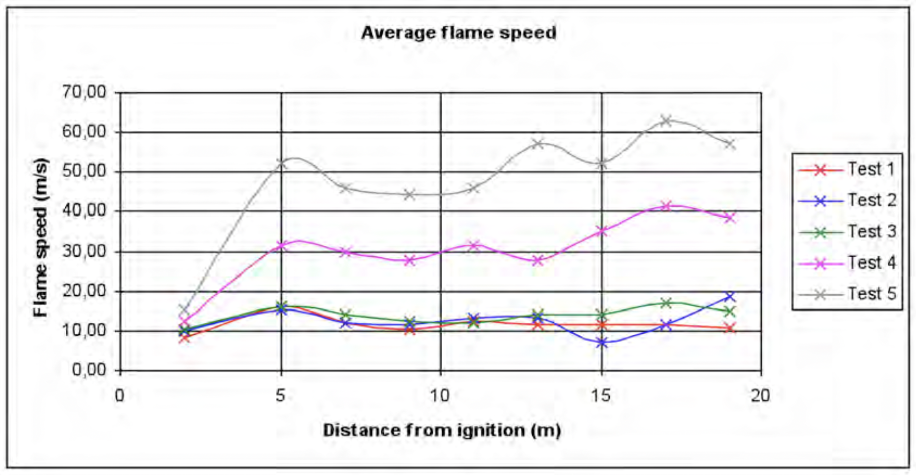
The results clearly show a strong difference of flame speeds obtained in the presence of larger bushes obtained from the direct surroundings of the test site and those obtained in an “empty” facility. The maximum flame speeds seen for the empty tent are 10-15 m/s. Only a marginal increase is observed for small bushes. In the presence of the larger bushes maximum flame speeds of 41 m/s and 63 m/s are observed indicating a considerable increase. Distinct flame accelerations are seen in all tests after ignition. In the case of the small bushes these accelerations are marginal, but in the case of the larger bushes, the flame speeds clearly increase in the second half of the experimental set-up, demonstrating a flame accelerating effect of vegetation.The pressure measurements only showed a small increase of pressure. For the P2 and P3 positions, pressure increases related to the second phase of flame acceleration of magnitude 2-6 mbar for test 4 and approximately 5-10 mbar for test 5, respectively. This is not surprising as explosion severity (source pressure) is strongly dependent on scale, and the limited volume and flame run-up distances in the experiments pale in comparison to what existed during the incident at Buncefield.
Concluding remarks
The Buncefield depot was a unique installation in that dense vegetation in the form of trees and bushes was present. Using the explosion simulator FLACS, the geometry of the Buncefield site was modeled including the dense vegetation. A large, shallow, heavier-than-air gas cloud was defined to cover part of the site and surroundings. After ignition, the flame front reached the dense vegetation and accelerated through the trees along the surrounding roads, resulting in high overpressures of several bar being generated by FLACS. These overpressures were consistent with observed blast damage after the incident. In addition, FLACS simulations predicted strong convective flow towards the ignition source similar to the observed blast damage indicators verified after the incident. We believe this is the first time the effect of trees on explosions has been demonstrated by 3D analyses.
To further demonstrate the validity of these results, a set of experiments was performed to show that congestion caused by dense vegetation could cause strong flame accelerations. The test volume consisted of a plastic tunnel, 20 m long with a semi-circular cross-section 3.2 m in diameter allowing for representing lanes of vegetation. The total volume of the tent was approximately 80.4 m3. The experimental program involved different degrees of vegetation size, vegetation density (blocking ratio) and number of vegetation lanes (over the full length of the tunnel). The main conclusions of the study are that trees can have an influence on flame acceleration in gas-air clouds, and that advanced models such as FLACS can be used to study such influence.
About the authors

Scott Davis, Ph.D., PE, CFEI
CEO – Principal Engineer @ Gexcon US
Dr. Scott Davis specialises in mechanical and aerospace engineering, and the engineering analysis and testing of combustion, thermal, and fluid processes. Dr. Davis applies his expertise to the investigation, prevention, and risk assessment of fires, explosions, and dispersion hazards such as flammable vapours and toxic exposures. Dr. Davis is a principal member of the NFPA 59A technical committee and provides key training in Gexcon’s advanced safety courses on major hazards, which includes LNG safety. Dr. Davis has published over 100 papers and is a regular speaker at process safety conferences.
Peter Hinze, Ph.D.
Dr. Peter Hinze specialises in the application of mechanical engineering principles to the analysis and investigation of automotive systems, industrial processes, fires, and explosions. He has investigated fires and explosions involving vehicles, industrial and manufacturing processes, and residential appliances. Dr. Hinze has particular experience investigating fires associated with automobiles, heavy equipment, motorcycles, and trucks, where common fire scenarios include post-collision fires, vehicles involved in fires in garages and other structures, and fires that occur while the vehicle is being operated. Dr. Hinze also applies the CFD software FLACS for consequence modeling.
Olav Roald Hansen
Founder @ HYEX Safety AS
Olav has a physics degree from NTNU and has worked with explosion modelling and FLACS since 1993. In the 1990s he was a FLACS developer with a particular focus on validation against experiments and made a FLACS training course. In the 2000s he was Gexcon R&D Director in charge of the FLACS development team and global sales until he started Gexcon US in 2008-2010.
Since 2012 Olav has worked as a consultant for GL (2012-2013) and LR (2014-2020). After starting HYEX Safety in June 2020 he has been working full-time with consulting work within hydrogen safety. Model validation and accuracy in CFD predictions have been a key focus in his work, and he is the author of numerous articles related to FLACS.
Kees van Wingerden, Ph.D.
VP Industrial Risk, Senior Principal Consultant @ Vysus Group
Dr. Wingerden holds a PhD from the University of Bergen, Norway and an MSc from the Delft University of Netherlands. He has 43 years of experience related to gas and dust explosions. He has also been involved in numerous accident investigations. He is heavily involved in standardization work and has written numerous articles on explosion safety. At the 16th International Loss Prevention Symposium 2019, Kees received an award for outstanding contribution to the advancement of process safety from the European Process Safety Centre (EPSC).
References
(1) Bakke, J.R. and R.W. Brewerton (2008), Buncefield Explosion Analysis, GexCon report no. GexCon-08-40419-RA-1, rev 04 (company confidential).
(2) Hansen O.R., Wilkins B.A. (2003), Oil mist explosions in a test channel, 37th Annual Loss Prevention Symposium, March 31-April 2, New Orleans.
(3) Moen, I.O., M. Ronato, R. Knystautas and J.H. Lee (1980), Flame Acceleration Due to Turbulence Produced by Obstacles, Comb. Flame, 39, pp. 21-32.
(4) Hjertager, B.H., Fuhre, K, Parker, S.J. and Bakke, J.R. (1984), Flame acceleration of propane-air in a large-scale obstructed tube, Progress in Astronautics and Aeronautics, 94: 504-522, AIAA Inc. New York 5 Harris, R.J. and M.J. Wickens (1989) Understanding Vapour cloud explosions – an experimental study, 55th autumn meeting of The Institution of Gas Engineers.
(6) Van Wingerden, C.J.M. (1989), Experimental investigation into the strength of blast waves generated by vapour cloud explosions in congested areas, Sixth Int. Symp. on Loss Prevention and Safety Promotion in the Process Industries, June 19-22, Oslo, Norway.
(7) Arntzen, B. J. (1998) Modelling of turbulence and combustion for simulation of gas explosions in complex geometries, Dr. Ing. Thesis, NTNU, Trondheim, Norway.
(8) Van den Berg, A.C. (1985) The multi-energy method. A framework for vapour cloud explosion blast prediction, J. Haz. Mat, 12, pp. 1-10.
(9) Tang, M.J. and Q.A. Baker (2000) Comparison of blast curves from vapor cloud explosions, Journal of Loss Prevention in the Process Industries 13 (2000) 433–438.
(10) Makhviladze, G. (2007) Hydrocarbon releases into the open atmosphere, case studies. Two-phase releases: Ufa catastrophe; Course notes: Explosion Prediction and Mitigation, University of Leeds; 11-15 July 2007.
(11) Van Wingerden, M. and Wilkins, B. (2008) Experimental investigation of the effect of flexible obstructions on flame propagation in vapour cloud explosions, GexCon report no. GexCon-08-F44110-RA-1, rev 01.


