

Support at the early stages of the project can highlight areas where risks could be reduced and help inform the design, making it more economical and cost-effective.
A ventilation and dispersion study was performed for a test cell using the computational fluid dynamics software package, FLACS. The aim of the study was to determine whether a Zone 2 of Negligible Extent could be assigned within the test cell.
Location
A leading car manufacturer, UK
Objectives
To assist a leading car manufacturer in reducing process risk and demonstrating risk to be as low as reasonably practicable (ALARP).
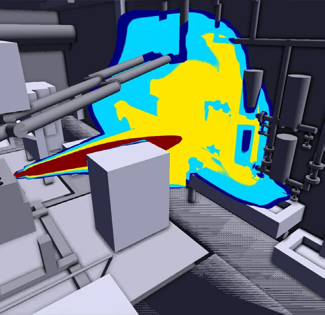
Pressurised jet release on fuel supply line
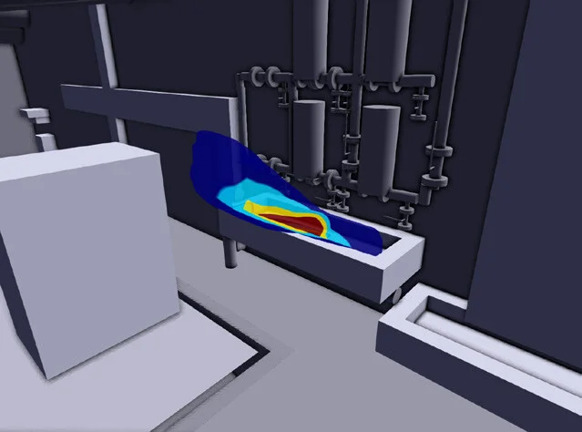
Ventilation dispersion within the pit volume, where red indicates ventilation dead spots
Task
- Workshop with key stakeholders to identify and define credible release scenarios to be considered in the study. Ventilation arrangement and emergency response (including detection system) defined.
- Creation of a 3D geometrical model of the test cell within FLACS.
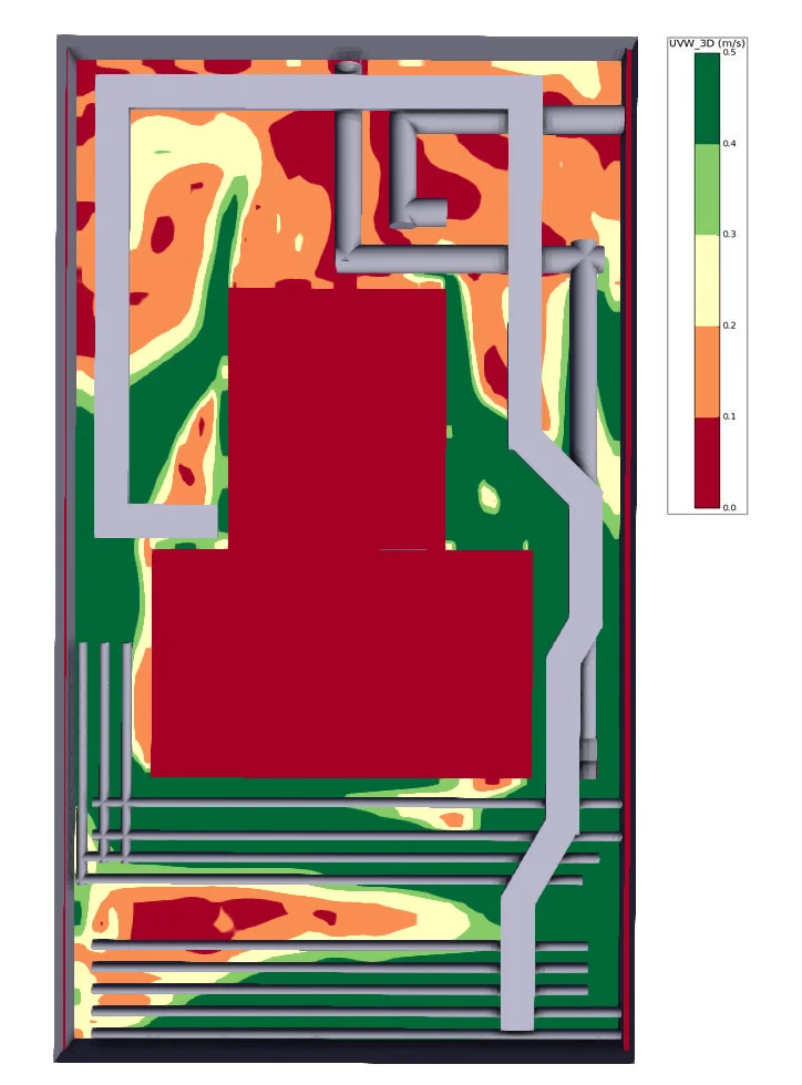
- Ventilation study to assess the normal operating conditions within the test cell to determine whether ‘dead spots’ may be present. Ventilation air flow reviewed at various heights, including within the pit volume, to determine whether accumulation of a hazardous flammable atmosphere in the event of a leak may occur.
- Model credible release scenarios including formation of liquid pools of fuel with subsequent evaporation and dispersion of a flammable vapour cloud.
- Monitor flammable vapour concentration at each of the detector sample points throughout the simulation run time. Detector sample point locations reviewed to ascertain whether detection would occur prior to a hazardous flammable atmosphere being achieved.
- Model enhanced ventilation conditions triggered on detection of a flammable vapour. Assess the impact of increased ventilation on dilution of the flammable atmosphere within the test cell.
- Monitor the size of the flammable vapour cloud throughout the simulation run time.
Approach
Ventilation modelling allows user to review flow of air throughout the area considered.
Useful for “complex geometries” – where the presence of obstacles and structures may create dead spots in the ventilation domain (areas with limited or no air movement).
Assess the dispersion of vapours including both vapour releases and evaporation of vapours from a liquid pool.
Dispersion modelling determines dilution of release and potentially hazardous zone extents, reviews the impact of varying ventilation flow rate and allows optimisation of gas detector system design.
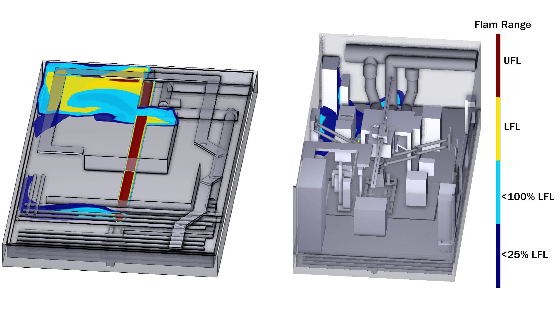
Dispersion of flammable vapour cloud generated following liquid release into pit volume
Ventilation
General good ventilation observed around the location within the main test cell. Dead spots were identified within the pit volume.
At the second detection point, where general ventilation was turned off, the flammable vapour cloud increased.
Dispersion
A series of dispersion scenarios were modelled considering the fuel supply lines.
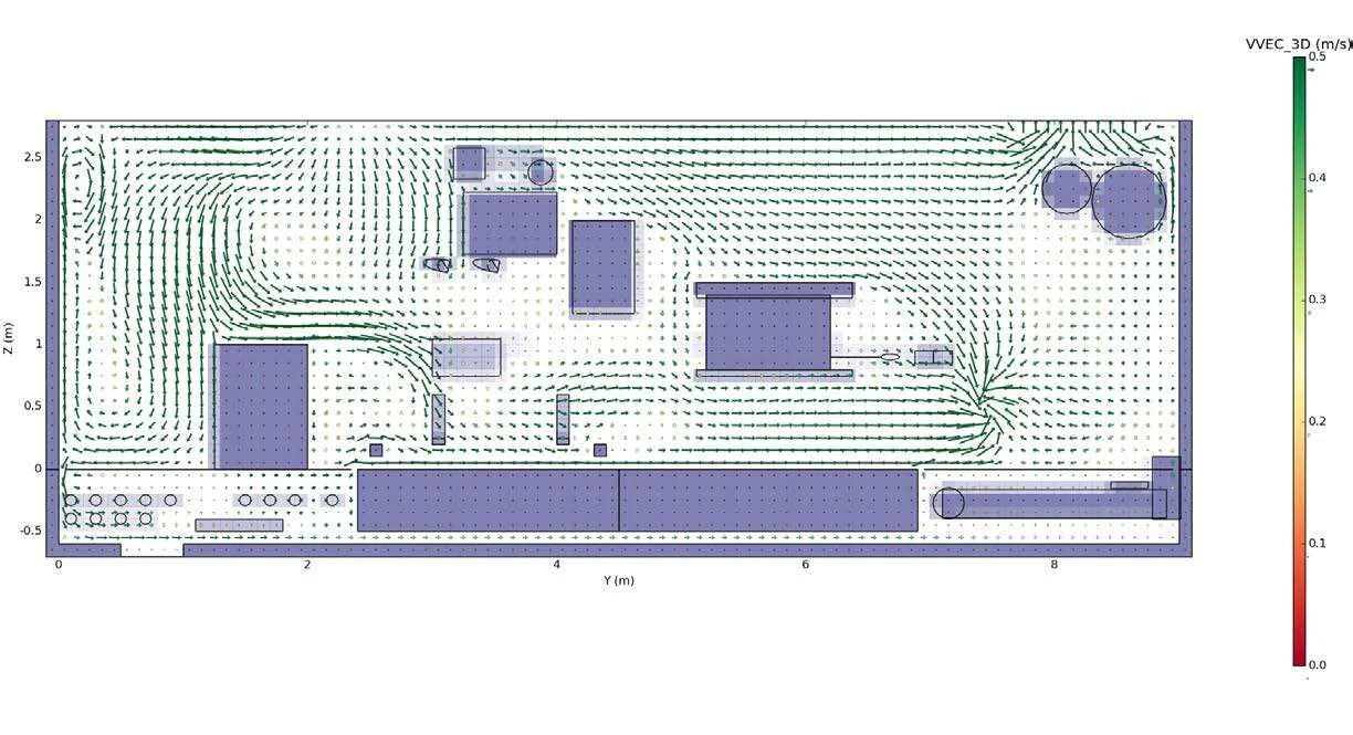
Vector plot showing ventilation within main test cell volume
Results
Scenario 1: Release from fuel supply lines into test cell, which form a pool within a drip tray.
- The small release modelled was detected quickly, due to optimal location of detector sample point (positioned in proximity to connections on fuel line).
- Local exhaust ventilation (LEV) in proximity to connections on fuel line. LEV provided by ATEX certified fan, which is activated at first detection set point 10% LFL (Lower Flammability Limit).
- Enhanced ventilation effectively diluted the flammable vapour cloud.
- Flammable atmosphere remains below second detection set point (25% LFL).
- Flammable atmosphere (above LFL) localised to drip tray.
Dispersion of flammable vapour cloud for Scenario 1: Liquid release into drip tray
Scenario 2: Release from fuel lines within FuelExact box, which forms a pool within a drip tray underneath.
- The release was detected quickly, primarily due to the geometry of the FuelExact box above the drip tray creating a channelling effect. This promoted directional flow of the flammable vapour towards the detector sample point (positioned above the corner of the drip tray).
- Second detection set point (25% LFL) activated almost immediately following release.
- Local exhaust ventilation (LEV) in proximity to the detector sample point activated. LEV provided by ATEX certified fan.
- Enhanced ventilation controls dispersion of flammable vapour and flammable atmosphere localised to drip tray.
Scenario 3: Release from connection on fuel supply line into engine, which forms a pool within the sump
- The modelling showed that a small release of fuel, which collects within the sump channel underneath the engine test pallet would not be detected by the proposed detector sample point locations.
- Detector sample points located within pit volume and at test cell ceiling level.
- Flammable atmosphere (>LFL) predicted within sump channel along centreline of test cell pit volume.
- Dedicated ventilation within pit volume (supplied via an ATEX certified fan) would be activated on detection of 10% LFL within test cell.
- However flammable release was not detected at any of the detection sample point locations.
- Flammable atmosphere expected within pit volume at back of test cell (along the adjoining wall with control room).
- 25% LFL cloud expected within main test cell volume, which remains undetected.
Summary
Generally, good ventilation was observed around the main test cell.
Dispersion studies determined that some vapour releases were detected promptly and were effectively diluted by the proposed design.
There were locations within the sump where there is a potential for dead spots. Ventilation configurations to promote effective dilution of flammable atmosphere were recommended.
Recommendations were provided including a review of the detector sample point locations, to optimise detection of a release into the sump.
Gexcon were able to provide feedback to the client on the design of the facility, prior to construction. Recommendations were based on analysis of site-specific potential releases, agreed with the client.
Risk reduction measures were reviewed against the hierarchy of controls, to demonstrate that the risk are as low as reasonably practicable.